

Hertel Lab · UMass Amherst · Undergraduate research
Muon veto for
superfluid-helium research.
I integrated an external muon veto for a superfluid-helium experiment, working from detector signals through analog conditioning, coincidence logic, data acquisition, and Python analysis.
- My role
- System integration, electronics, acquisition & analysis
- Research advisor
- Scott Hertel
- Research period
- February 2025 – May 2026
- Thesis status
- Analysis and writing in progress
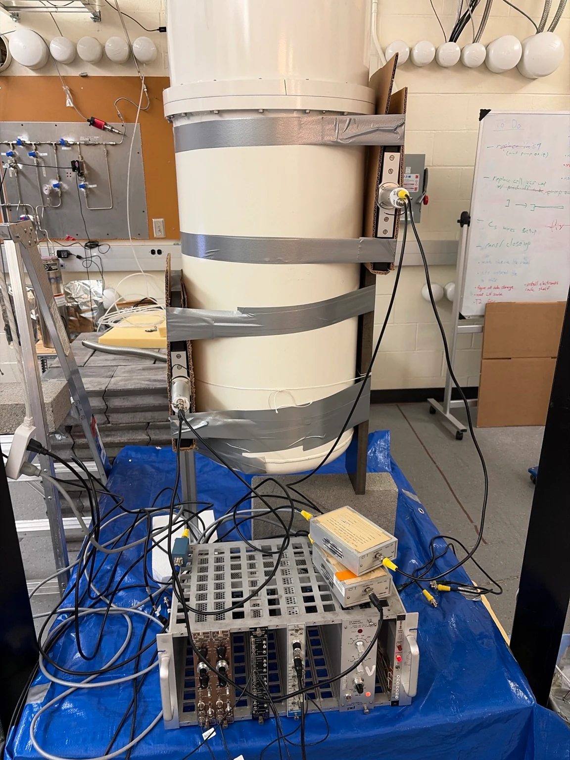
01 / The physics question
Give a delayed signal a starting time.
Cosmic-ray muons pass through the laboratory and can deposit energy in a helium detector. In superfluid helium, that energy can produce excited helium molecules, He2*, including long-lived triplet states. Studying the delayed response requires a way to identify when a muon passed through.
The veto provides an external timing reference. Coincident scintillator signals tag a candidate muon passage so its time can be compared with waveforms from the cryogenic experiment.
Experimental context
The helium detector operates in a cryogenic environment around 10 mK. My work concerned the external veto and its electronics, acquisition, and analysis; the refrigerator and dark-matter detector were part of the broader laboratory experiment.
02 / Detector & electronics
Connect the hardware into a useful measurement.
The system uses prebuilt Eljen Technologies PVT scintillator paddles, supplied with ET Enterprises photomultiplier tubes already attached. My contribution began with integrating those detector assemblies into the experiment.
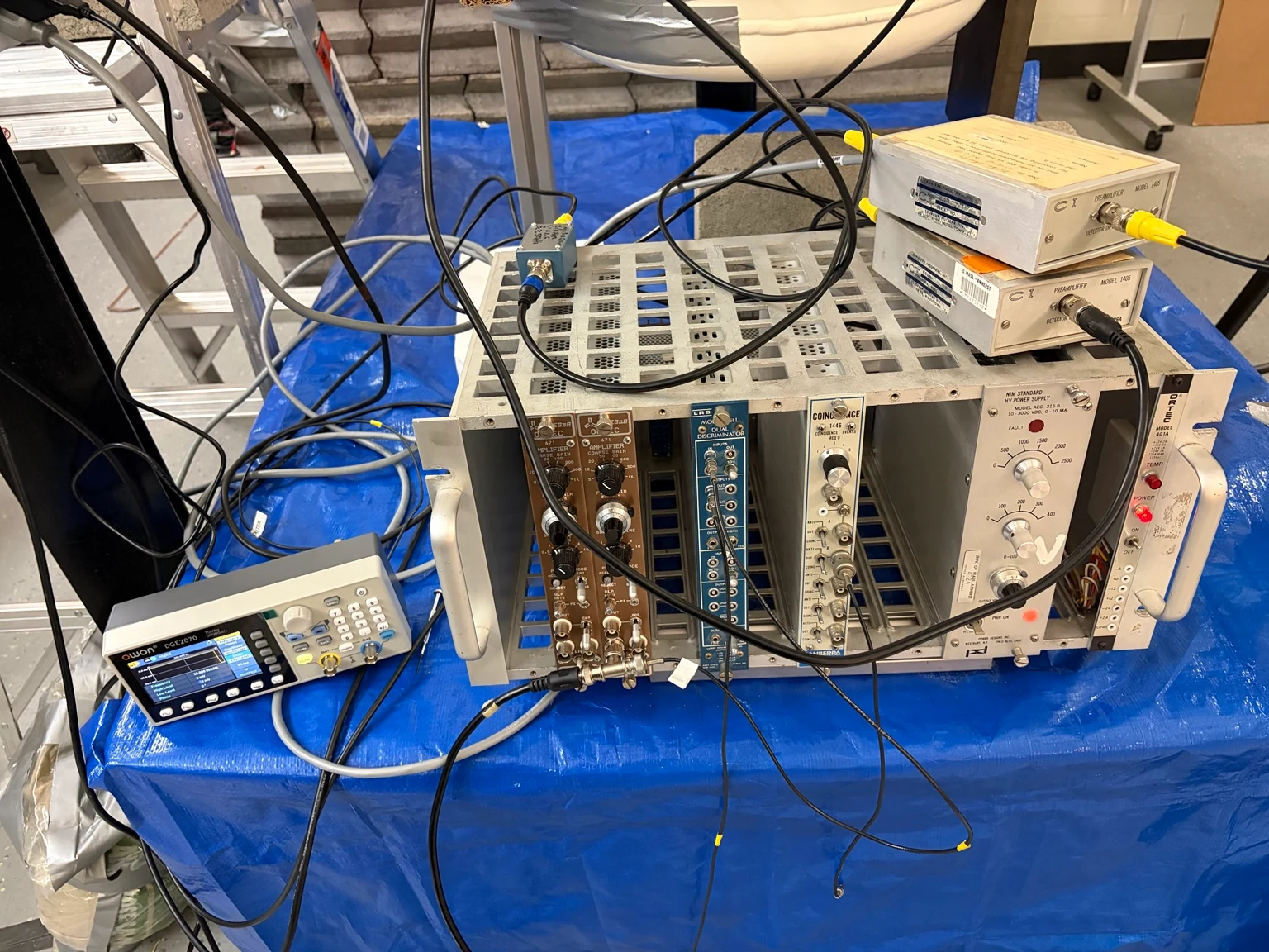
I worked across high-voltage signal handling, NIM electronics, coincidence logic, and National Instruments acquisition. The coincidence stage identifies signals close together in time, on an approximately 1 μs timing scale, before those tags are used in the event workflow.
- Detector integrationBring the supplied scintillator/PMT assemblies into the veto and trigger chain.
- Signal conditioningDesign, solder, and integrate an RC high-pass filter between an amplifier and discriminator.
- Acquisition & analysisConnect the electronics to NI acquisition and develop multichannel waveform processing in Python.
03 / Analog signal conditioning
A small circuit with a specific job.
A discriminator turns an analog detector signal into a logic decision. The waveform presented to that input matters: slow changes and offsets need to be considered alongside the pulse being detected.
I designed and soldered an RC high-pass filter, then integrated it between the amplifier and discriminator. Its purpose was to condition the detector signal before threshold discrimination.
- 01 Amplifier
- 02 RC high-pass filter
- 03 Discriminator
Separate slow variation from faster structure.
A series capacitor and shunt resistor attenuate slowly varying components relative to higher-frequency components. For an ideal, unloaded first-order RC high-pass circuit:
τ = RC
fc = 1 / (2πRC)
These equations describe the circuit principle. The installed component values and a measured transfer response are not reported here.
Why the choice of time constant matters
The time constant sets the transition between attenuated and transmitted frequency components. Choosing it means considering the desired pulse shape as well as slower baseline behavior. A high-pass stage can also alter pulse shape, so its usefulness has to be assessed in the complete signal chain.
Source and load impedances can change the response from the ideal circuit above. The schematic explains the design; it does not establish the response of the assembled experimental system.
Circuit background: TI Precision Labs — RC circuits (PDF) (opens in a new tab)Constructing this stage made the connection between circuit behavior and detector timing concrete: a logic pulse is only as useful as the analog signal that produced it.
04 / Acquisition & analysis
Keep the waveform, then examine the timing.
National Instruments hardware connects the detector and trigger electronics to the acquisition workflow. Event waveforms are stored in HDF5, preserving multichannel data for processing rather than reducing each event to a single trigger label.
I developed Python/HDF5 routines for waveform baselines, pulse identification, and event timing. The analysis proceeds from individual traces toward event matching and time-difference distributions.
- Read the event
Load the relevant HDF5 waveform channels and inspect their baselines and pulse structure.
- Identify candidate pulses
Extract pulse times while keeping the waveform and analysis choices available for review.
- Compare event times
Match candidate events and examine Δt distributions between the external tag and detector response.
05 / Evidence & current status
A working research chain, with the analysis still open.
This project connects hands-on electronics to a scientific question. The work I can demonstrate includes integration of the supplied detectors, construction of an analog conditioning stage, NIM/DAQ integration, and Python waveform-processing tools.
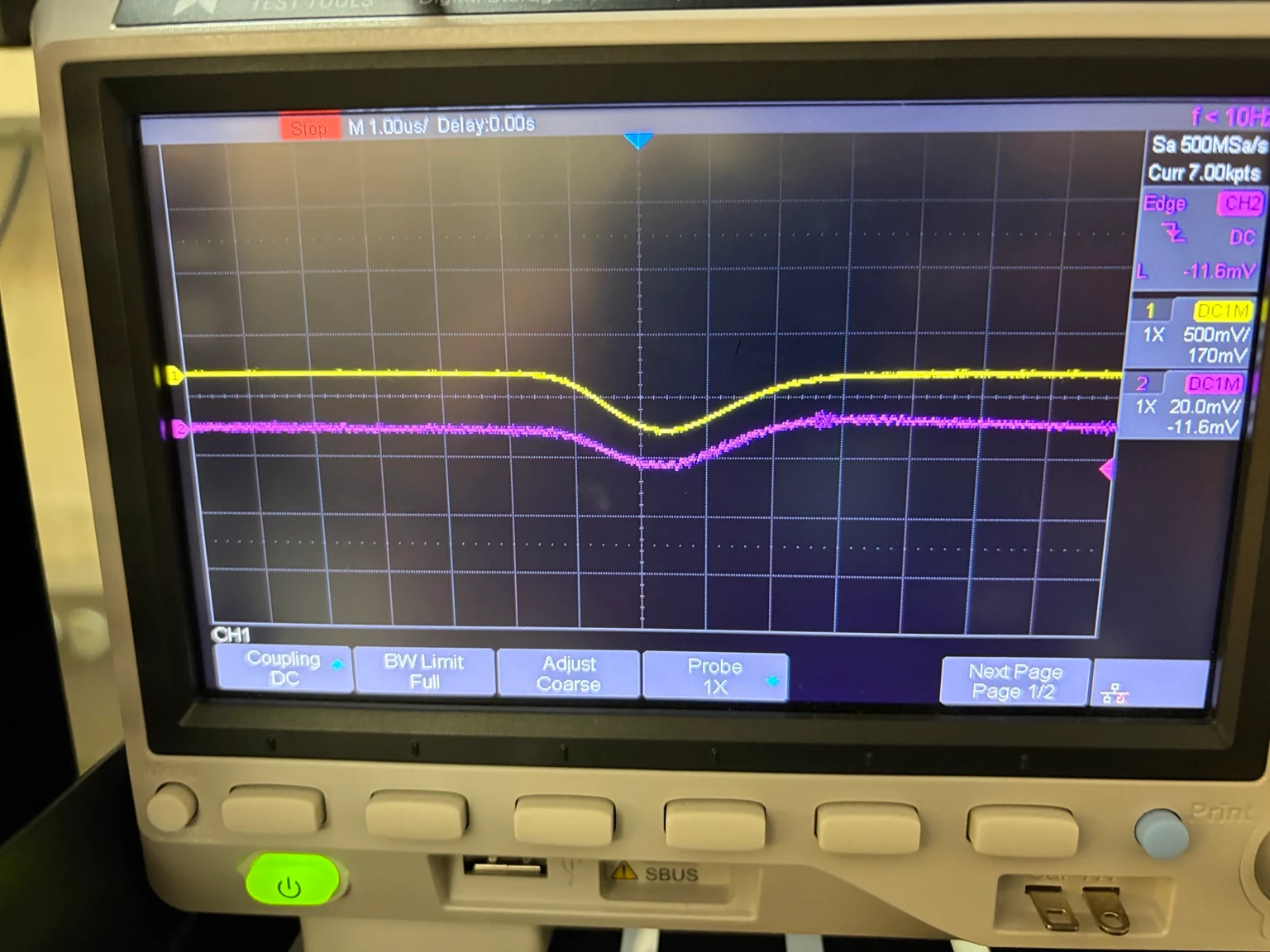
The thesis analysis and manuscript remain in progress. The photographs document apparatus and signal checks; they do not establish a final veto efficiency, a measured filter improvement, or an excimer lifetime.
Undergraduate thesis
Construction of Muon Veto System for Studying Excimer Triplet Dynamics in Superfluid Helium-4
Analysis and writing in progress.